3D Scanning: A valuable tool for Infrastructure Upgrade Projects
At CAW, we strive to innovate and use the latest methods and technologies to provide service excellence and long-term value to our customers. 3D scanning is one of the tools we use, alongside Building Information Modelling (BIM) technology to enhance the accuracy and efficiency in the planning and execution of infrastructure projects and upgrades. Currently, CAW is applying 3D Modelling and BIM Technology to delivery three Upgrade Projects at the Ringsend WwTP:
• Upgrade of the Ultrafiltration (UF) Membrane Plant from its current output capacity of 33m3 / hour to 66m3 / hour, reducing the WwTP’s dependency on potable water.
• Design, Supply and Installation of an additional 1MWe Containerised CHP Unit.
• UV Disinfection Facility Upgrade Project at Ringsend.
By creating precise digital representations of facilities and infrastructure at every project stage—before, during, and after completion—3D scanning enables us to optimise workflows, reduce risks, and deliver better outcomes for our customers. This article explores the benefits and practical applications of 3D scanning.
What are the advantages of using 3D Scanning technology?
There are several advantages to using 3D Scanning technology to create 3D representations within infrastructure construction and upgrade projects:
- Enhanced accuracy and quality control.
- Improved efficiency and cost savings.
- Enhanced planning and design.
- Improved communication and collaboration.
- Risk management and safety improvements.
- Comprehensive Documentation.
How does the process work for an infrastructure upgrade?
Pre-design phase
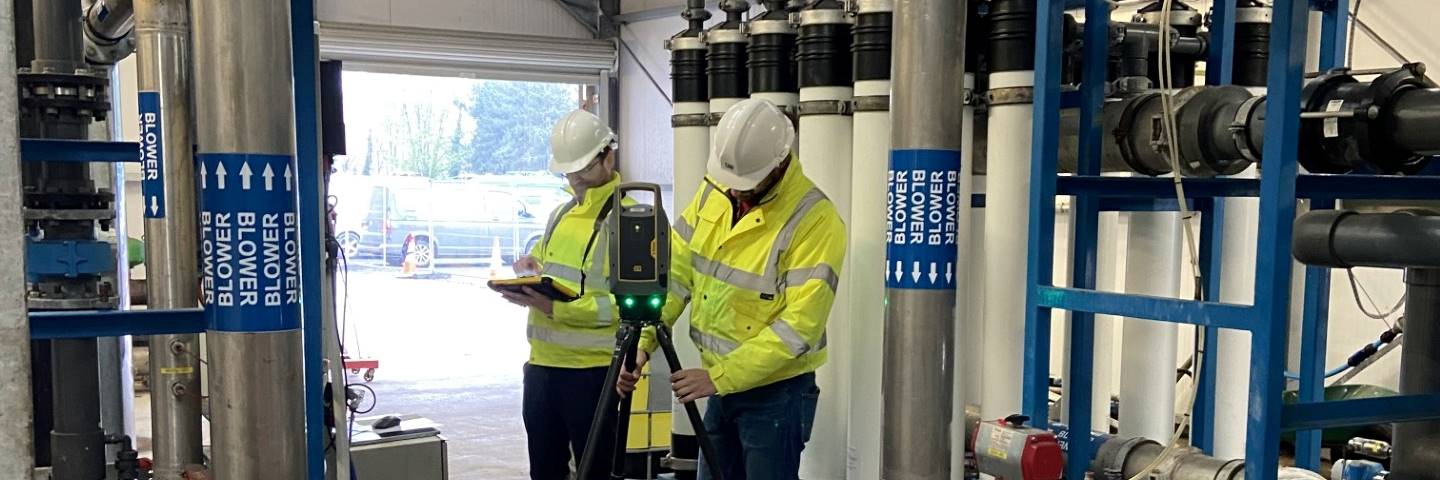
During the design phase of the project, a 3D scan is taken of the existing facility using CloudScan technology.
A 3D scanner is used to create detailed digital representations of facilities. The scanner is moved around the facility to capture images and data from various angles, both inside and outside the building. It uses laser technology to measure the distance to each point in its field of view, capturing millions of points to create a “point cloud” representation of the facility.
Alongside the laser measurements, the scanner also takes numerous high-resolution photographs. These images combine to create a 360-degree picture at each position where the scanner stands. The point cloud data and the 360-degree pictures are sent to a connected device, such as a tablet, for initial processing and visualisation. This detailed point cloud and the additional 360-degree images provide a highly accurate and immersive view of the scanned area.
Technology in action
We share an example of the technology in action below, as we start the design phase of a Ringsend Ultrafiltration (UF) membrane bank upgrade to double the current capacity of 33³ per hour to 66³ per hour to further reduce the requirement for fresh potable water.
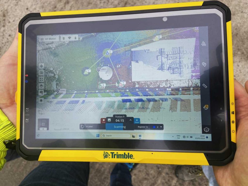
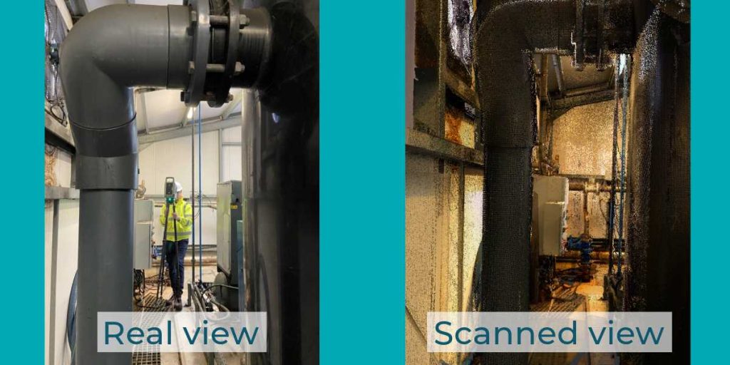
Each area highlighted in the tablet view below shows each location 3D mapping has been captured. The CloudScan technology recalibrates all the information to connect all the 3D images into an overall 3D visual.
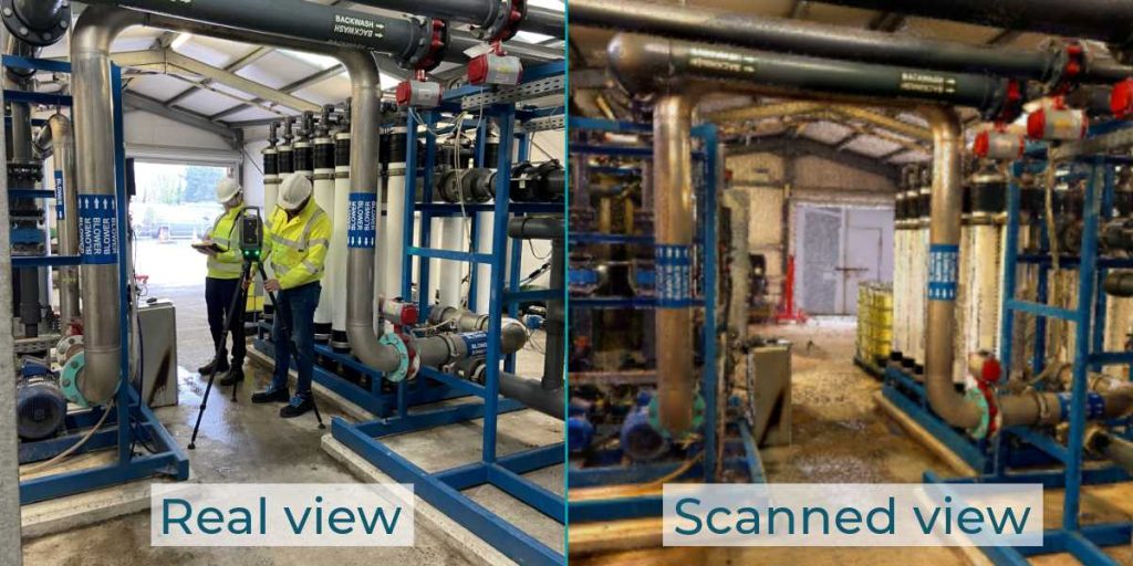
The images below show just how detailed and accurate the captured images are. What’s more, the software allows navigation and viewing of all areas within the three-dimensional view, a feature not afforded by the more conventional 2D static image.
Design Phase
Once complete the scans are imported into the 3D Building Information Modelling Software. The 3D model is created by starting with the building infrastructure, such as the floors, walls, and roof through to the internal structure, and equipment, working through every level of detail down to the smallest details such as cables and switches, etc.
This creates a starting point for the design phase. The initial upgrade design will be added to the 3D model with the ability to show the plan, views and documentation.
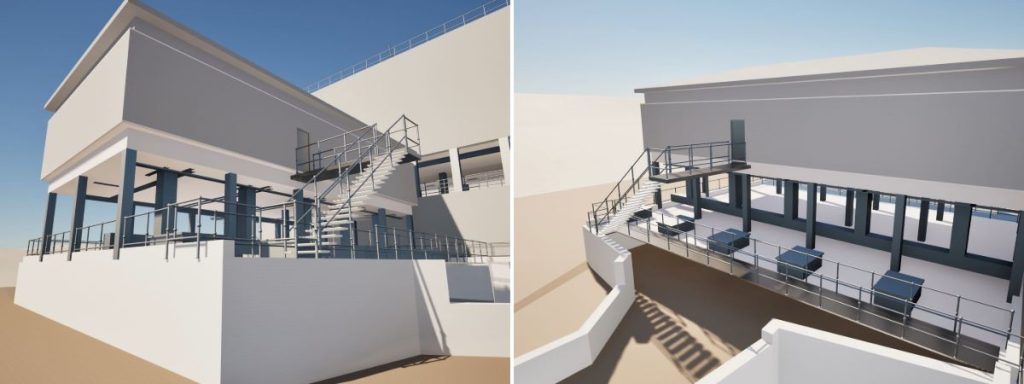
Below is an example of a 3D model created at the start of the UV Disinfection Facility Upgrade Project at Ringsend. At the date of this article, this project is in the design phase.
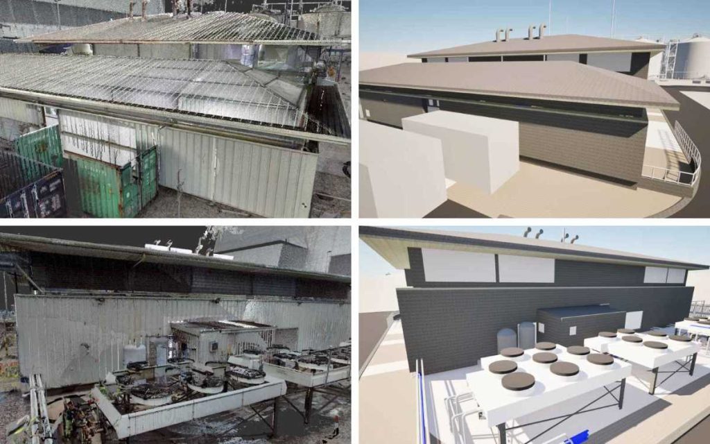
We have also recently started working on a Containerised Unit for a new CHP engine. You can see here how the scan is used to create a 3D model, over which a 3D design for the new infrastructure is added. The table below shows a 3D scan, the 3D “Before Model” and the proposed 3D Design Model for the Containerised CHP Unit, from the side and rear of the building.

Construction phase
The construction phase for these projects commenced using the 3D design model and associated documentation. As the Construction Phases progress, larger variations and changes are recorded and captured on the 3D Model and a Final 3D Model will be generated upon Construction Completion will capture all changes and variations both large and small.
Commissioning phase
Upon Construction Completion, another final full Cloud Scan will be taken which will be cross checked against the latest 3D model to identify any variations that have not been captured or logged during the construction phase of the projects and where inaccuracies in the 3D Model are identified, these will be amended to ensure that all details of the final constructed installation are fully captured.
Handover
On completion of the project, a final “Digital Twin” model will be provided to the client which represents the exact model and specifications.
Within the model, not only geometrical information but also non-geometrical information (such as manufacturer information or installation date, warranty information, etc) will be provided to the client.
This process benefits providers, clients, and operators by delivering an accurate model of the facility. Relying solely on drawings cannot guarantee complete accuracy, but 3D scanning ensures precise and reliable representations.
Follow us on LinkedIn to stay posted on the progress of the Ultrafiltration Membrane Bank upgrade and the UV Disinfection Facility Upgrade projects that we are managing at Ringsend WwTW.

